Engine Support Beam
Sure, you can buy an off the shelf support beam, or use 4x4 wood beams. Or you can make up your own for around $35 plus 1/2 hour labor, save yourself some money and have pride in making your own tool. All parts from your local hardware store. My beam is still going strong after 17 years and dozens of clutch jobs working on SHOs for a living. Have only just had to replace the main beam after it developed a kink around one of the bolt holes.
Introduction
Made of galvanized steel pipe, this beam is more than adequate to support the engine and is useful if you want to drop the subframe or remove the engine and/or transmission. It is tee-shaped with a rear beam across the engine compartment with a hook and chain going through the rear driver's side lower intake manifold support bolt, and a tee beam that goes from the rear beam, over the lifting eye (attached to the beam with another hook), and rests on the front cross member.
Dimensions are for both Gen I and Gen II.
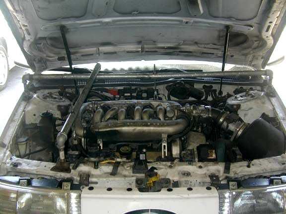
This is how it looks sitting on top of the engine. You’ll need rags or whatever under the feet to protect the paint. I have leather coasters cut in half under the feet:
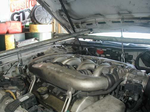
The next picture shows how the hooks attach to the engine. Note how there’s plenty of hook above the beam to enable the engine to be tilted to facilitate removing the transmission:
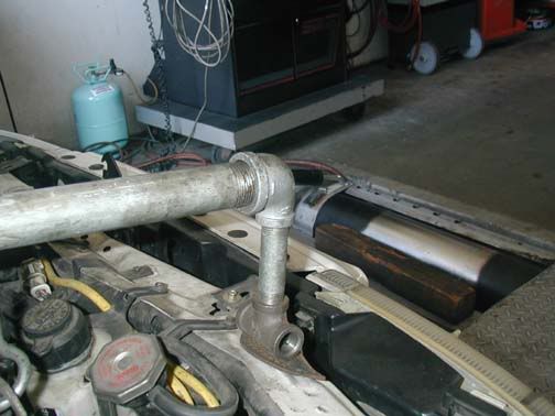
The next picture shows the assembly of the foot at the front of the engine. The feet at the sides are the same except that the vertical pipe is a little shorter:
Parts Needed
- Rear Crossbeam: one length of 1 " i/d (1 1/2" o/d) galvanized pipe that is 54.5" long for a Gen I or Gen II. Have the store cut the pipe to length and thread both ends. You need to be accurate on this measurement as the feet rest on the hood gullies that are only 1" wide.
- Tee beam: one length of 1" i/d galvanized pipe 32" long. Have the store cut to length and thread one end. This gets bolted onto to the rear beam and extends to the front of the engine compartment over the engine lifting eye. This is around 1- 1.5" longer than you really need, but you may want to use this on other cars, so this way you have a bit of flexibility.
Then from the parts bins:
- Three 1" to 1/2" elbows to attach the legs.
- Two 1/2" pipe sections (threaded at both ends), each 3" long for the crossbeam legs.
- One 1/2" pipe section (threaded both ends), 4" long for the T leg that sits on the front cross member.
- Three 1/2" tee joints for the feet.
- Two 3/8" x 8" long eye bolts with the correct nut and washer which are used to support the engine. You will need to open these up in a vice so that they become hooks. Eye should be around 1.75" outside diameter. They will need to be 8" long to enable you to tilt the engine when getting the transmission out.
- One 12" length of chain with links big enough to go through these hooks and through an intake manifold support bolt. This is used to support the rear of the engine by removing the intake manifold support bracket nearest the driver and using the lower bolt as an anchor point for the chain.
- One 3.5" X 3/8" bolt with nut and two washers to join the T to the crossbeam.
- Thick Pads of some kind to go under the crossbeam feet. I use leather coasters. Thick shop towels will also work.
Tools Needed
- Electric drill, 3/8" drill bit for the hooks and 3/8" bolt.
- Hammer and center punch to stop the drill bit wandering when you drill the holes.
- A 1/2" socket drive extension bar used to tighten the elbows and tees.
- Large vice.
Assembly
You may want to use Loctite:
- Attach the elbows to the ends of the 1" pipes.
- Attach the legs to the elbows. The short legs go on the long pipe, the long leg goes on the short pipe.
- Attach the tees to the legs.
- Drill holes for the 8" long hooks and the 3/8" bolt. It's best to put your bars on the engine compartment, long one across the back behind the inlet manifold, short one roughly at right angles to the long one so that it rests on top of the crossbeam, passes directly over the engine hoist eye and the foot rests on a flat part of the front cross member. One hook is passed through the lifting eye. The other is attached to the lower manifold support bolt I mentioned earlier. Now you should know where to drill the holes.
- Attach the Tee to the crossbeam using the 3.5" bolt and a washer under the nut and the bolt head.
- Attach the hooks to the beams. Washer under the nut.
Installation
- Take off the inlet manifold support bracket nearest the driver. Place the support beam in position. Use plenty of padding under the feet. Remove the front hook, pass it through the engine lifting eye, and put it back on. Take up the slack by screwing on the nut until it is finger tight.
- Attach one end of the chain to the rear of the engine using the lower manifold support bolt where it goes into the engine block. Don't use the upper support bolt: you may put too much strain on the intake manifold.
- Make sure that the rear hook is near it's highest position (nut screwed almost all the way on), then attach the other end of the chain to the rear hook. Take up the slack by screwing on the nut until it is finger tight. Make sure you use shop towels to stop the inlet manifold from being scratched.
- You are now ready to begin work on removing the subframe, etc. You will be able to lower/tilt/raise the engine by adjusting the two nuts on the hooks once the subframe is removed.
- Make sure that the engine is supported from below after removing the transmission as a safety measure.
Original Procedure by:
Nick Chrimes
BaySHO Performance